Theory of Wide Band Deramping
- Aug 9 2021
- CoreEL Technologies

Introduction
Wide band signals in general refer to wide bandwidth chirp signals, the class of the chirp function may be Linear Frequency Modulation, where the frequency of the generated signal is varied linearly starting from an initial frequency. This could also be thought as a frequency spectrum centered around a carrier frequency. Wide band chirp signals are used in Radars based on the application, as some Radars use it solely for tracking and some use it for profiling. In this paper we present the basic theory of operation of Chirping and Dechirping.Any details on the frequency values, pulse width, bandwidths, generation methods of WB/Deramp waveforms/samples, frequency synthesis technique etc are not in the scope of this paper.
System Overview
Top level overview of a Typical Radar signal generation and reception units are depicted in Figure 1
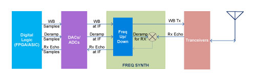
Figure 1: Top level overview of a typical Radar signal generators and receivers
Present day Radars use Digital resources like an FPGA or an ASIC or combination of both to generate Radar signals and to analyze echoes. In order to produce transmit signals, first Wide band signals at IF frequency can be generated using Digital to Analog conversion of LFM digital samples provided by FPGA and this might further get frequency synthesized to get the final Radar output signal. At the digital receiver side of the Radar, even to handle Intermediate Frequency Wide Band signal of the echo, more signal processing resources will be required as the entire bandwidth needs to analyzed and characterized. In order to simplify digital receivers, a method called Deramp processing can be applied. In this method, the received Radar echoes are mixed in analog domain with an LFM signal having the same chirp rate as the transmit LFM pulse. The Deramped pulses may then be frequency synthesized and sampled for processing in digital domain, the frequency content of the Deramped IF signal reflects the range of the targets.
As per Figure 1, FPGA generates digital samples for Wide band and Deramp, Wide band for Radar transmission and Deramp for receiver path signal processing. Most of the systems use external DACs for getting IF analog outputs of FPGA samples, newer FPGA devices are capable of achieving direct RF signal generation with inbuilt high speed DACs.
Properties of Transmit Signal
Transmit Radar signal is a pulsed LFM signal, where the frequency of the signal is changed linearly with respect to time within the transmit pulse. In order to represent mathematically/using visual diagrams, let us consider the pulse width of the signal be Ttw, the LFM signal be centered around frequency Ftc. Within the transmit pulse, the frequency of the transmit signal varies linearly with respect to time from (Ftc-Bt/2) to (Ftc+Bt/2). Ramp rate which is the slope of the frequency with respect to time within the transmit pulse duration can be treated as KHz/sec (for simplifying per say, we can consider the start of the transmit pulse as time t=0). With these conditions, the transmit signal's frequency function within the transmit window can be depicted in simple mathematical terms as shown in Equation 1 and the visualization of transmit signal frequency characteristic is depicted in Figure 2.
F(t) = F0 + Kt ----------(Equation 1)
- Here, t : Time within the transmit pulse duration with respect to starting point of the pulse
- F(t) : Out frequency response with respect to time
- F0 = (Ftc-Bt/2)
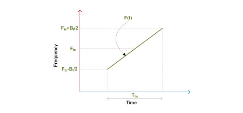
Figure 2: Transmit signal frequency vs time graph
Properties of Receive signal
If we consider a stationary target and the echo from it, the echo will have the same frequency characteristics as the transmitted signal but will be delayed in time and reduced in signal power based on the target range. The received echo frequency characteristics can be visualized sameas Figure 2. The frequency properties of received signals remain same as represented in Equation 1.
Properties of Deramp signal
Deramp is another pulsed LFM signal having the frequency characteristics similar to transmitted Radar pulse, here the slope of the frequency with respect to time within the pulse remains K Hz/sec; the pulse width and the bandwidth of the signal will be more than that of transmitted signal keeping the frequency ramp rate same. Let us assume the pulse width of the signal be Tdw, LFM centered around Fdc, frequency of the signal varies from (Fdc-Bd/2) to (Fdc+Bd/2), ramp rate which is slope of frequency vs time within the pulse duration remains same as K Hz/sec, we can represent the Deramp signal's frequency function within the active window (where pulse is generated) using simple mathematical terms as shown in the below formula and the visualization of Deramp signal's frequency characteristic is depicted inFigure 3.
Fd(t) = Fd0 + Kt ----------(Equation 2)
- Here, t : Time within the Deramp pulse with respect to starting point of the pulse
- Fd(t) : Out frequency response wrt time
- Fd0 = (Fdc-Bd/2)
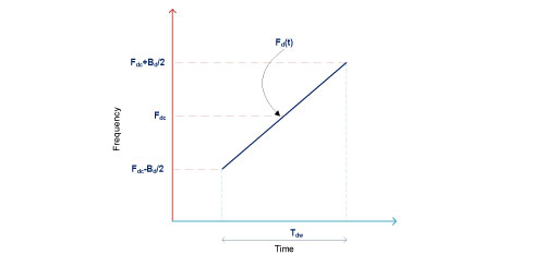
Figure 3: Deramp signal frequency vs time graph
Applying the concept of Deramping on echo signals
Let us consider that Deramp signal is generated during the receiving window of the Radar and we set the pulse width of the Deramp signal in such a way that the echo signal is completely contained within the active period of the Deramp signal as shown inFigure 4.
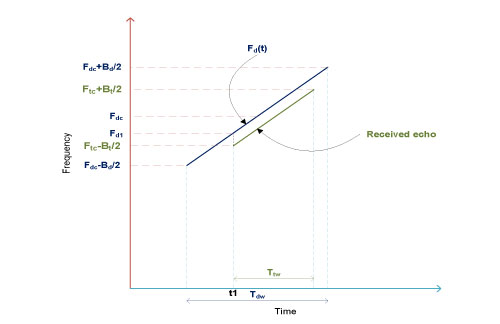
Figure 4: Frequency vs time graph for Deramping a received echo signal
Following points highlight the result of application of Deramp signal on a received echo signal.
- When an echo signal arrives at the radar receiver, assuming a stationary target, its starting frequency within the pulse shall be exactly same as that of Transmit signal. Soat time instance t1 the frequency of the received signal is (Ftc-Bt/2).
- As Deramp and the received echo have same LFM ramp rate, from the instance of reception of the echo signal, frequencies of Deramp and the echo signal maintain a constant gap
- From time instance t1 the amount of change in Deramp frequency is exactly same as the amount of change in the echo signal’s frequency until the echo pulse ends
- If we take the difference in frequencies of echo signal and Deramp signal, it should be a constant value. This constant vale is nothing but {(Ftc-Bt/2) – Fd1} Hz, considering subtraction of Deramp signal frequency from echo signal frequency
- If the Deramp signal and the received echo are applied to a mixer and use the difference sinusoid of the mixer output, the resultant signal will be a single tone.
- Suppose the echo comes a little early, then the frequency of the single tone output of the Mixer will be different, an example shown in Figure 5.
- If multiple echoes are received, each echo will result in a unique frequency component at the output of mixer depending on their time of arrival. An example as shown in Error! Reference source not found.Figure5, here in case of echo@t2 single tone frequency will be {(Ftc-Bt/2) – Fd2}; it will be {(Ftc-Bt/2) – Fd3} for the echo @ t3 and so on.
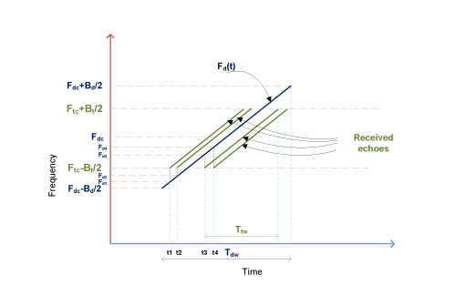
Figure 5: An example of receiving multiple echoes
Conclusion
The aim of this paper is to convey the information on basic principles of one of the Wide Band receiving schemes used in Radar receivers using minimal mathematical and trigonometric relationships. In order to simplify the information being conveyed, we have omitted the required frequency up/down conversions at any stage, as these are self implied. LFM up chirp is used in our examples, the same concept can be applied to LFM down chirp signals provided both transmit and Deramp signals use the same chirping mechanism.
|
Abbreviation |
Description |
|
FPGA |
Field Programmable Gate Array |
|
LFM |
Linear Frequency Modulation |
|
DAC |
Digital to Analog Converter |
|
ADC |
Analog to Digital Converter |
|
IF |
Intermediate Frequency |
|
RF |
Radio Frequency |
|
WB |
Wide Band |
|
ASIC |
Application Specific Integrated Circuit |